Sunday, April 2, 2017

K-Map representation


Digital Teaching AidKarnaugh Mapping - Lesson 4Lesson Plan(introduction...)IntroductionKarnaugh mapTruth table to Karnaugh mapPairs, Quads, and OctetsOverlapping and Rolling

Pairs, Quads, and Octets

Pairs


Fig. 4-4: Four variable simplification

As you see in Fig. 4-4, only one variable goes from uncomplement to complement. Whenever this happens, you can eliminate the variable that changes form.

Proof:

X = A B C

Ex:


Fig. 4-5: Pairs

Whenever you see a pair first encircle it and then simplify to get the simplified Boolean expression:


Quad


Fig. 4-6: Quad

Quad: A group of 4 one's that are horizontally or vertically adjacent. End to end or in form of a square.

A quad eliminates two variables and their complements.

Proof:

(two pairs)

X = A B (C + C)

X = A B

Encircle the quad and step through the different one's in the quad and determine which two variables go from complement to uncomplement (or vs), these are the variables that drop out.

Ex:


Fig. 4-7: Quad

The variables B and D can be eliminated. So we get the following equation:

X = A C


Octet


Fig. 4-8: Octet

An octet eliminates three variables and their complements.

Proof:

(two quads)

X = A (C + C)

X = A

Karnaugh Simplifications

Process:

1. Draw the Karnaugh map
2. Look for octets and encircle them.
3. Look for quads and encircle them.
4. Look for pairs and encircle them.
5. Simplify and write down the equation.


Ex:


Fig. 4-9: Karnaugh map


Overlapping and Rolling

Overlapping groups

Ex:


Fig. 4-10: Karnaugh map

Groups can overlap to get a simpler equation:


Rolling the map

Ex:


Fig. 4-11: Karnaugh map

Instead of encircling two pairs:


We can roll the map and encircle a quad:


HO: Simplify the following map.

Solution:


HO: Simplify the following map.

Solution:

Simplification Procedure for Karnaugh maps

Pair Reduction Rule : Remove the variable which changes its state from complemented to uncomplemented or vice versa.Pair removes one variable only.

Quad Reduction Rule : Remove the two variables which change their states.A quad removes two variables.

Octet Reduction Rule : Remove the three variables which changes their state.Octet removes three variables.

Map Rolling : Map rolling means roll the map considering the map as if its left edges are touching the right edges and top edges are touching bottom edges.While marking the pairs quads and octet, map must be rolled.

Overlapping Groups : Overlapping means same 1 can be encircled more than once. Overlapping always leads to simpler expressions.

Redundant Group : It is a group whose all 1's are overlapped by other groups. Redundant groups must be removed. Removal of redundant group leads to much simpler expression.


Ex. 1 : Represent the following boolean expression in a K-map and simplify.

F = x'yz + x'yz' + xy'z' + xy'z

Solution :

The K-map is as follows :

Hence the simplified expression is

F = x'y + xy'

Ex. 2 :Simplify the following boolean expression using K-map.

F = a'bc + ab'c' + abc + abc'

Solution :

The K-map is as follows :

Hence the simplified expression is

F = bc + ac'


Wednesday, March 22, 2017

Types of DC generators

Generally DC generators are classified according to the ways of excitation of their fields. There are three methods of excitation.
  1. Field coils excited by permanent magnets – Permanent magnet DC generators.
  2. Field coils excited by some external source – Separately excited DC generators.
  3. Field coils excited by the generator itself – Self excited DC generators.
A brief description of these type of generators are given below.

Permanent Magnet DC Generator
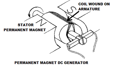
permanent magnet dc generatWhen the flux in the magnetic circuit is established by the help of permanent magnets then it is known as Permanent magnet DC generator.
It consists of an armature and one or several permanent magnets situated around the armature. This type of DC generators generates very low power. So, they are rarely found in industrial applications. They are normally used in small applications like dynamos in motor cycles.

Separately Excited DC Generator

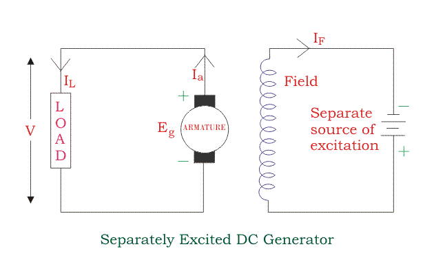
These are the generators whose field magnets are energized by some external dc source such as battery .
A circuit diagram of separately excited DC generator is shown in figure. Ia = Armature current IL = Load current V = Terminal voltage Eg = Generated emfseparately excited dc generatorVoltage drop in the armature = Ia × Ra(R/sub>a is the armature resistance) Let, Ia = IL = I (say) Then, voltage across the load, V = IRa Power generated, Pg = Eg×I Power delivered to the external load, PL = V×I.

Self-excited DC Generators

These are the generators whose field magnets are energized by the current supplied by themselves. In these type of machines field coils are internally connected with the armature. Due to residual magnetism some flux is always present in the poles. When the armature is rotated some emf is induced. Hence some induced current is produced. This small current flows through the field coil as well as the load and thereby strengthening the pole flux. As the pole flux strengthened, it will produce more armature emf, which cause further increase of current through the field. This increased field current further raises armature emf and this cumulative phenomenon continues until the excitation reaches to the rated value. According to the position of the field coils the self-excited DC generators may be classified as…
  1. Series wound generators
  2. Shunt wound generators
  3. Compound wound generators

Series Wound Generator

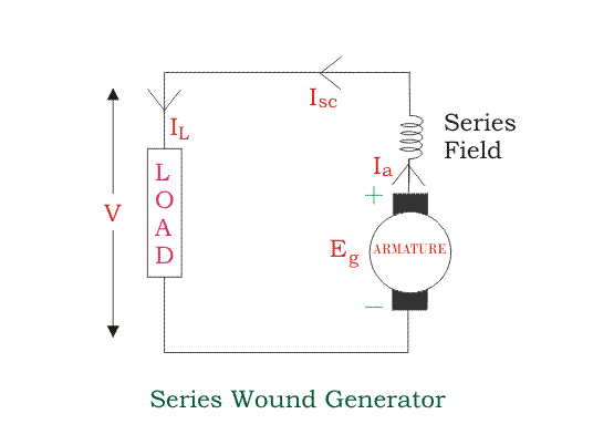
In these type of generators, the field windings are connected in series with armature conductors as shown in figure below. So, whole current flows through the field coils as well as the load. As series field winding carries full load current it is designed with relatively few turns of thick wire. The electrical resistance of series field winding is therefore very low (nearly 0.5Ω ). Let, Rsc = Series winding resistance Isc = Current flowing through the series field Ra = Armature resistance Ia = Armature current IL = Load current V = Terminal voltage Eg= Generated emfSeries Wound DC GeneratorThen, Ia = Isc = IL=I (say) Voltage across the load, V = Eg -I(Ia×Ra) Power generated, Pg = Eg×I Power delivered to the load, PL = V×I

Shunt Wound DC Generators

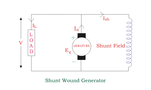
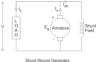
In these type of DC generators the field windings are connected in parallel with armature conductors as shown in figure below. In shunt wound generators the voltage in the field winding is same as the voltage across the terminal. Let, Rsh = Shunt winding resistance Ish = Current flowing through the shunt field Ra = Armature resistance Ia = Armature current IL = Load current V = Terminal voltage Eg = Generated emfshunt wound dc generatorHere armature current Ia is dividing in two parts, one is shunt field current Ish and another is load current IL. So, Ia=Ish + IL The effective power across the load will be maximum when IL will be maximum. So, it is required to keep shunt field current as small as possible. For this purpose the resistance of the shunt field winding generally kept high (100 Ω) and large no of turns are used for the desired emf. Shunt field current, Ish = V/RshVoltage across the load, V = Eg-Ia RaPower generated, Pg= Eg×Ia Power delivered to the load, PL = V×IL

Compound Wound DC Generator

In series wound generators, the output voltage is directly proportional with load current. In shunt wound generators, output voltage is inversely proportional with load current. A combination of these two types of generators can overcome the disadvantages of both. This combination of windings is called compound wound DC generator. Compound wound generators have both series field winding and shunt field winding. One winding is placed in series with the armature and the other is placed in parallel with the armature. This type of DC generators may be of two types- short shunt compound wound generator and long shunt compound wound generator.
Short Shunt Compound Wound DC Generator
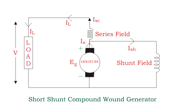
The generators in which only shunt field winding is in parallel with the armature winding as shown in figure.short shunt compound wound generatorSeries field current, Isc = IL Shunt field current, Ish = (V+Isc Rsc)/RshArmature current, Ia = Ish + IL Voltage across the load, V = Eg - Ia Ra - Isc RscPower generated, Pg = Eg×Ia Power delivered to the load, PL=V×IL
Long Shunt Compound Wound DC Generator
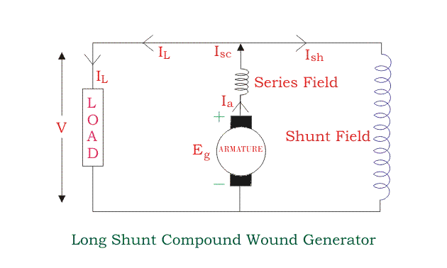
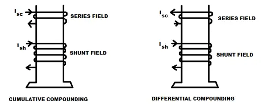
The generators in which shunt field winding is in parallel with both series field and armature winding as shown in figure.long shunt Compound wound generatorShunt field current, Ish=V/RshArmature current, Ia= series field current, Isc= IL+Ish Voltage across the load, V=Eg-Ia Ra-Isc Rsc=Eg-Ia (Ra+Rsc) [∴Ia=Ics] Power generated, Pg= Eg×IaPower delivered to the load, PL=V×ILIn a compound wound generator, the shunt field is stronger than the series field. When the series field assists the shunt field, generator is said to be commutatively compound wound. On the other hand if series field opposes the shunt field, the generator is said to be differentially compound wound.commulatively differentially compound
vbn

Characteristic of Shunt Wound DC Generator

In shunt wound DC generators the field windings are connected in parallel with armature conductors as shown in figure below. In these type of generators the armature current Iadivides in two parts. One part is the shunt field current Ish flows through shunt field winding and the other part is the load current IL goes through the external load. shunt wound generatorThree most important characteristic of shunt wound dc generators are discussed below:
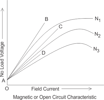

Magnetic or Open Circuit Characteristic of Shunt Wound DC Generator

This curve is drawn between shunt field current(Ish) and the no load voltage (E0). For a given excitation current or field current, the emf generated at no load E0 varies in proportionally with the rotational speed of the armature. Here in the diagram the magnetic characteristic curve for various speeds are drawn.
Due to residual magnetism the curves start from a point A slightly up from the origin O. The upper portions of the curves are bend due to saturation. The external load resistance of the machine needs to be maintained greater than its critical value otherwise the machine will not excite or will stop running if it is already in motion. AB, AC and AD are the slops which give critical resistances at speeds N1, N2 and N3. Here, N1 > N2 > N3.

Critical Load Resistance of Shunt Wound DC Generator

This is the minimum external load resistance which is required to excite the shunt wound generator.magnetic or open circuit characteristic

Internal Characteristic of Shunt Wound DC Generator

The internal characteristic curve represents the relation between the generated voltage Eg and the load current IL. When the generator is loaded then the generated voltage is decreased due to armature reaction. So, generated voltage will be lower than the emf generated at no load. Here in the figure below AD curve is showing the no load voltage curve and AB is the internal characteristic curve.

External Characteristic of Shunt Wound DC Generator

AC curve is showing the external characteristic of the shunt wound DC generator. It is showing the variation of terminal voltage with the load current. Ohmic drop due to armature resistance gives lesser terminal voltage the generated voltage. That is why the curve lies below the internal characteristic curve. The terminal voltage can always be maintained constant by adjusting the of the load terminal.external charateristics of shunt dc generator
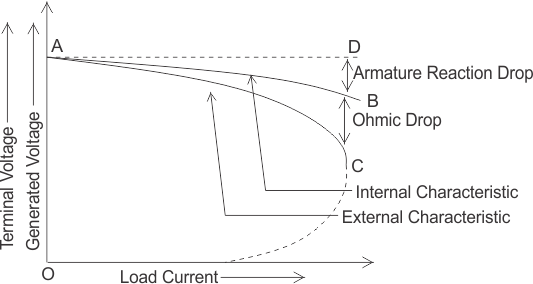
When the load resistance of a shunt wound DC generator is decreased, then load current of the generator increased as shown in above figure. But the load current can be increased to a certain limit with (upto point C) the decrease of load resistance. Beyond this point, it shows a reversal in the characteristic. Any decrease of load resistance, results in current reduction and consequently, the external characteristic curve turns back as shown in the dotted line and ultimately the terminal voltage becomes zero. Though there is some voltage due to residual magnetism.
We know, Terminal voltage
Now, when IL increased, then terminal voltage decreased. After a certain limit, due to heavy load current and increased ohmic drop, the terminal voltage is reduced drastically. This drastic reduction of terminal voltage across the load, results the drop in the load current although at that time load is high or load resistance is low.
That is why the load resistance of the machine must be maintained properly. The point in which the machine gives maximum current output is called breakdown point (point C in the picture).

Friday, March 17, 2017

Need to understand

shekharkhatiwara1994.blogspot.comYou need to understand life enough and at the same time be ready to endure the consequences of your actions, because every action of life comes with a reward.
Unknown

Saturday, March 11, 2017

Constructional Features
Figure 35.1 shows a sectional view of a 4-pole D.C machine. The length of the machine is
perpendicular to the paper. Stator has got 4 numbers of projected poles with coils wound over it.
These coils may be connected in series in order that consecutive poles produce opposite
polarities (i.e., N-S-N-S) when excited from a source. Double layer lap or wave windings are
generally used for armature. Essentially all the armature coils are connected in series forming a
closed armature circuit. However as the coils are distributed, the resultant voltage acting in the
closed path is zero thereby ensuring no circulating current in the armature. The junctions of two
consecutive coils are terminated on to the commutator segments. Stationary carbon brushes are
placed physically under the center of the stator poles touching the rotating commutator segments.

Now let us examine how a D.C voltage is obtained across the brushes (armature
terminals). Let us fix our attention to a particular position in space. Whichever conductor is
present there right now, will have some definite induced voltage in it (dictated by e = blv). In
course of rotation of the armature newer conductors will occupy this position in space. No
matter which conductor comes to that particular position at any given point of time, it will have
same voltage induced in it. This is true for all the positions although the magnitude and polarity
of the voltages in different position may be different. The polarity of the voltage is opposite for
conductor positions under north or south pole. Remembering that all the conductors are
connected in series and brushes are suitably placed for obtaining maximum voltage, the
magnitude of the voltage across the brushes will remain constant.
To understand the action of the commutator segments and brushes clearly, let us refer to
the following figures (35.3 and 35.4) where a simple d.c machine working as generator are
shown with armature occupying various positions. Armature has got a single rectangular coil
with sides 1 and 2 shown in detail in figure (35.2). The two terminals 1 and 2 of the coil are
firmly joined to commutator segments C1 and C2 respectively. Commutator segments C1 and
C2, made of copper are insulated by mica insulation shown by lines between C1 and C2 and
rotate along with the armature.

Karma Kelvin Dorji Inspires with His Generous and Philanthropic Work: Helps Those in Need Through Social Service Program.

Karma Kelvin Dorji is inspiring a lot of people by his generous and philanthropic work. Hailing from Trashi Yangtse, Karma was formally a mo...