j flop is an important basic memory element for digital circuit. Flip-flop is designed by assembling different logic gates. Single logic gate does not have any information storing capacity but by combining different such gates one can make such a digital circuit which can store digital information. Flip flop is such circuit. There are different types of flip flop with different characteristics for different application. Flip-flop is the basic building blocks of most sequential circuits. Flip-flop (FF), is also known as a bistable multivibrator, because it has two stable states. It y6zaætwgdxtcan remain in d of the states indefinitely. Its state can be changed ny applying the proper triggering signal. Flip flop is one-bit memory element. There are two outputs in a flip-flop generally marked as Qh and  . Either of Q and can be used as output but normal practice is to take Q as output port and as inverted output port.
It is to be noted here that a flip flop has always one out complement of other output. The state of a flip-flop is normally determined by the condition of output Q. If Q = 1 the flip-flop is said to be in HIGH state or logic 1 state or SET state. When, Q = 0 the state of flip flop is said to be in LOW state or logic 0 state or RESET state or CLEAR state. The figure below shows a block diagram of a flip flop. It shows a flip-flop may have one or more inputs but only two outputs. The combination of inputs which alter the outputs or state of flip flop is referred as excitation. The excitation is used to switch the flip flop from one state to other. But the typical feature of flip flop is that once the state of flip flop is changed by applying, excitation, it remains unaltered even the excitation is removed from input ports. Hence, momentary application of excitation is enough to change the state a flip-flop. This is how flip flop behaves as memory element. When, Q = 1 it stores a 1 and when, Q = 0, it stores a 0. Flip-flops are the basic components of shift registers and counters. Flip flop is a sequential circuit hence it can be either synchronous or asynchronous. When inputs are controlled by clock pulse it is normally referred as flip flop. Here the inputs are applied but not acted until clock pulse appears and enable the inputs. When the same circuit is made asynchronous that is its inputs is not controlled by clock pulse, it is called latch. It is SET or RESET instantaneously on receiving the input signal. Latch can act independently of clock signal.
Most simple type of flip flop is S R Flip Flop. It has two inputs S and R and two outputs Q and  . The state of this latch is determined by condition of Q. If Q is 1 the latch is said to be SET and if Q is 0 the latch is said to be RESET. This S R Latch or Flip flop can be designed either by two cross-coupled NAND gates or two-cross coupled NOR gates. When we design this latch by using NOR gates, it will be an active high S-R latch. That means it is SET when S = 1. When we design this latch by using NAND gates, it will be an active low S-R latch. That means it is SET when S = 0. S R Flip Flop is also called SET RESET Flip Flop. Figure below shows the logic circuit of S R latch.
 In the above logic circuit if S = 1 and R = 0, Q becomes 1. Let us explain how.
NOR gate always gives output 0 when at least one of the inputs is 1.So when S is applied as 1 the output of gate G2 i.e. is 0 irrespective of the condition of second input Q to the gate.Now is input of gate G1 so both the inputs of G1 become 0 as R is already 0. So, output of G1 is now  or 1.So whatever may be the previous condition of Q, it always becomes Q = 1 and = 0 when, S = 1 and R = 0. This is called SET condition of the latch.In the above logic circuit if S = 0 and R = 1, Q becomes 0. Let us explain how.As we already said, a NOR gate always gives output 0 when at least one of the inputs is 1.So when R is applied as 1, the output of gate G1 i.e. Q is 0 irrespective of the condition of second input to the gate.So, whatever may be the previous condition of Q, it always becomes 0 this 0 is then fed back to input of gate G2. As here S is already 0, both inputs of G2 are 0. Hence output of G2 i.e. will be 1. So, Q = 0 and = 1 when, S = 0 and R = 1. This is called RESET condition of the latch.In the above logic circuit if S = 0 and also R = 0, Q remains same as it was. Let us explain how.First suppose Q is previously 1.Now the inputs of G2 are 0 and 1 as S=0 and Q=1. So output of G2 i.e. is
  or 0.Now both inputs of G1 are 0 as R=0 and =0. So output of G1 i.e. Q is or 1.Now suppose Q is previously 0.Now both inputs of G2 are 0 and 1 as S=0 and Q=0. So output of G2 i.e. is or 1.Now the inputs of G1 are 0 and 1 as R=0 and =1. So output of G1 i.e. Q is or 0.So it is proved that Q remains same as it is when S = 0 and also R = 0 in S R latch or flip flop.
In the above logic circuit if S = 1 and also R = 1, the condition of Q is totally unpredictable. Let us explain how.
First suppose Q is previously 1.Now both inputs of G2 are 1 as S=1 and Q=1. So output of G2 i.e. is  or 0.Now the inputs of G1 are 1 and 0 as R=1 and =0. So output of G1 i.e. Q is
  or 0. That means Q is changed.Now Q is 0. So inputs of G2 are 1 and 0 as S = 1 and Q = 0. So output of G2 i.e. is or 0. That means is unchanged.Now the inputs of G1 are 1 and 0 as R=1 and =0. So output of G1 i.e. Q is or 0. That means Q is unchanged.So, when both S and R are 1, it becomes unpredictable whether the value of output Q will be changed or unchanged. This condition of S R latch normally avoided. As the latch is SET when S = 1(HIGH), the latch is called Active High S R Latch. There is other type of latch which is SET when, S = 0 (LOW), and this latch is known as Active Low S R Latch.
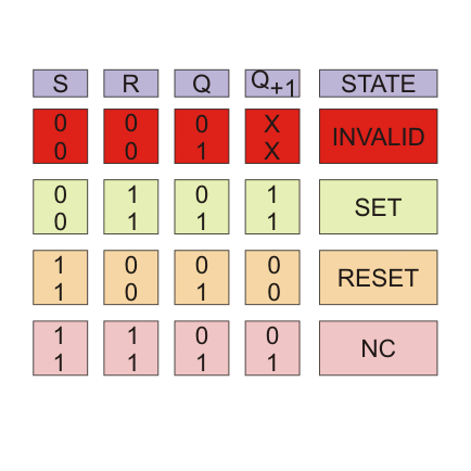


No comments:
Post a Comment